Potential Relay Troubleshooting
Operating And Troubleshooting Potential Or Voltage Relays 2018 03 05 Achrnews

Know Your Potential Starting Relays

Troubleshooting The Hvac Potential Relay Youtube
Ice Breaker Troubleshooting Potential Relays

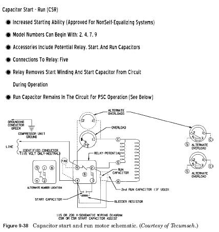
10 3 Potential Relays 10 4 Solid State Starting Relays And Devices 10 5 Motor Bearings 10 6 Motor Drives Components For Electric Motors

Refrigerator Potential Relay Refrigerator Troubleshooting Diagram

Replacement relays can be cross referenced for different manufacturers using convenient tables via the internet.
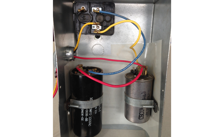
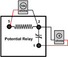
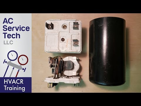
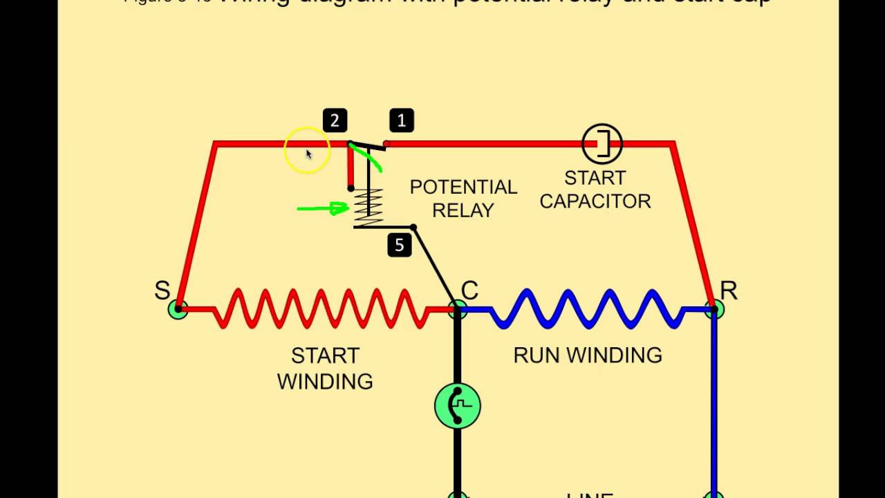
Potential relay troubleshooting.

Ice Breaker Troubleshooting Current Relays 2012 09 03 Achrnews

Potential Type Relay Hvac Troubleshooting

Hvac Motor Start Relays Hvac Troubleshooting
Potential Relays What Happened To Terminal 3 Hvac Training Solutions
Symptom Cause Troubleshooting

Troubleshooting A Faulty Potential Relay On A Residential Ac Youtube

Potential Relay Part 1 Youtube

Troubleshooting Hvac Capacitors Hvac Easy Repair Tips 101

Capacitors Refrigerator Troubleshooting Diagram

Start Capacitors For Hvac Compressors Motor Start Assist

How To Test A Potential Relay Part 1 Youtube
Testing A Bad Honeywell General Purpose Relay And Taking Apart To See The Burn Marks Youtube
Potential Relays Commercial Refrigeration Youtube
Hermetic Compressor Motor Types Hvac Troubleshooting

Ptcr Relay Youtube

Using Current Transformers With Current Sensing Relays
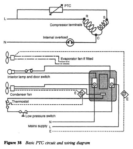
Refrigerator Positive Temperature Coefficient Refrigerator Troubleshooting Diagram

55 New Potential Relay Wiring Diagram A Govern Relay Is Used In The Automotive Indus In 2020 Electrical Circuit Diagram Electrical Wiring Diagram Trailer Light Wiring
Https Encrypted Tbn0 Gstatic Com Images Q Tbn 3aand9gcrht1nm2la3185zcrwbmme0csijyochrkhgyjhbtxe Usqp Cau

Start Capacitor Problem Electrical Diy Chatroom Home Improvement Forum

Wrg 8228 Potential Relay Wiring Diagram In 2020 Diagram Relay Electronic Parts
More Electric Motor Starting Run Capacitor Troubleshooting Faqs

Troubleshooting Challenge A Split System That S Not Cooling 2014 03 10 Achrnews

Start Capacitor Wiring Diagram In Starting Electrical Wiring Diagram Capacitors Electrical Circuit Diagram
Source : pinterest.com
